Developing a Robust MEMS Process: From Device Requirements to a Stable Process Window
How measurable outputs, controlled experiments and realistic variation turn a promising recipe into a dependable fabrication process.
A fabrication recipe can produce an acceptable wafer and still represent a weak process. It proves that one combination of material condition, tool state, geometry and handling worked once. It does not prove that the next wafer will behave the same way.
That distinction matters in MEMS fabrication because lithography, deposition, etching, polymer processing, release, bonding and packaging are tightly coupled. Each operation inherits conditions from earlier steps and creates constraints for those that follow. A resist profile that looks acceptable after development may still be unsuitable for lift-off. A film that meets its thickness target may carry enough residual stress to deform a released structure. An etch that reaches the required depth may leave a surface condition that compromises bonding.
Robust development therefore begins with the device requirement, not with a familiar recipe or a convenient tool parameter. What must the finished structure achieve? Which fabricated outputs determine that behavior? How much variation can be tolerated before function or yield becomes unacceptable?
Only then should parameter optimization begin. The task is to establish a trustworthy baseline, map process dependencies, prioritize variables, design decisive experiments and locate an operating window that remains acceptable under realistic variation.
Engineering principle
A recipe defines setpoints. A robust process defines acceptable outputs, allowable variation, measurement methods and the response to deviation.
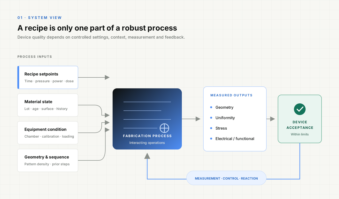
A successful run is not yet a stable process
It helps to separate three levels of maturity.
A successful run demonstrates feasibility under one particular combination of conditions. It proves that an acceptable result can be produced, but says little about the size of the acceptable operating region.
A repeatable recipe produces similar results when the same conditions are recreated over a limited period. This is stronger evidence, but it may still depend on one material lot, one chamber state, one wafer geometry or one experienced operator.
A robust process continues to meet its requirements when relevant inputs vary within defined limits. Its critical outputs are measurable, its important sources of variation are understood, and its response to deviations is documented.
Early MEMS development often involves small sample sizes and expensive wafers, so certainty develops gradually. The important discipline is to state exactly what has been demonstrated and what remains untested.
1. Begin with the device, not the recipe
The natural temptation during process development is to begin at the equipment interface: exposure dose, gas flow, chamber pressure, spin speed, bake temperature or deposition power. These are convenient variables because they are directly adjustable. They are not, however, the definition of success.
The correct starting point is the function of the device.
For a suspended structure, critical outputs may include thickness, uniformity, residual stress and stress gradient. For an electrode, they may include linewidth, thickness, sheet resistance, contact resistance and continuity. For multilayer integration, overlay and interface quality may matter more than the isolated quality of either layer.
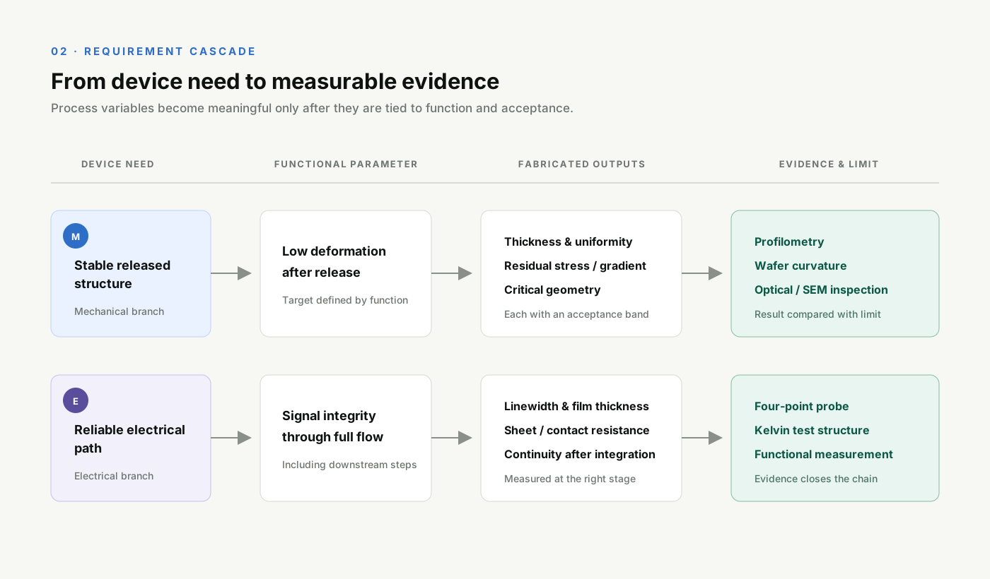
The development objective should therefore be written as a chain:
Device requirement -> functional parameter -> fabricated feature -> process output -> measurement
| Device need | Critical fabricated output | Possible evidence |
|---|---|---|
| Mechanically stable released structure | Thickness, residual stress, stress gradient, geometry | Profilometry, wafer curvature, optical displacement, SEM |
| Reliable electrical path | Linewidth, film thickness, continuity, contact resistance | Four-point probe, Kelvin structure, probe-station measurement |
| Complete structural release | Remaining sacrificial material, residue, deformation, stiction | Optical inspection, SEM, profilometry, functional motion |
| Accurate multilayer integration | Overlay error, enclosure, interface condition | Alignment vernier, microscope metrology, cross-section |
“Improve lithography” is too vague to guide an experiment. “Maintain the critical dimension within its acceptance band while achieving a sidewall profile compatible with the next deposition step” is a process-development objective.
Decision rule
Do not optimize a parameter until the output it is expected to improve - and the method used to measure that output - have been defined.
2. Map the process chain before changing setpoints
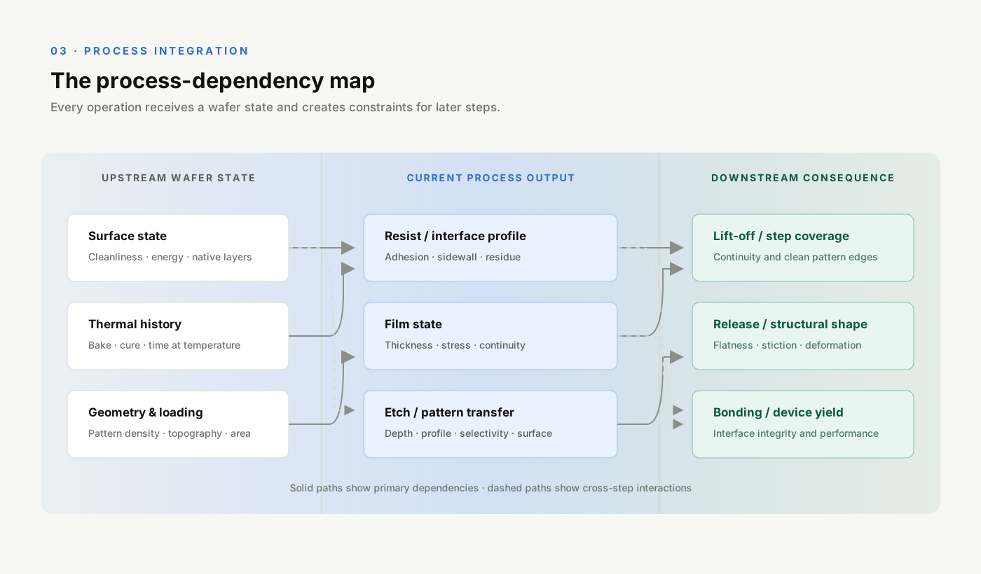
MEMS process development is a systems problem. The output of one step is the input condition of the next, and the most influential dependency may cross several operations.
Surface preparation can affect coating uniformity, thin-film adhesion or bonding later in the flow. Thermal history can change polymer cross-linking, dimensional stability and residual stress. Lithographic sidewalls influence lift-off and step coverage. Pattern density can change local etch behavior. A cleaning step can improve one interface while attacking another material already on the wafer.
This is why an individually “good” step can still be wrong for the device. Maximum adhesion is not automatically desirable if the layer must later be removed selectively. Maximum etch rate is not automatically useful if it reduces selectivity or worsens profile control. The thickest possible mask is not automatically safer if it degrades alignment or introduces difficult stripping conditions.
A practical dependency map should show the condition received from upstream processing, the outputs created, the later steps that depend on them, and where each critical output is inspected.
This perspective also changes how process limits are chosen. A parameter range should not be accepted solely because the immediate step looks good. It must remain compatible with the complete sequence.
Research on transferring production-oriented methods into MEMS development emphasizes this same shift: the object being developed is not only the device, but also the fabrication process that must be maintained and advanced over time.1
3. Establish a baseline that can be trusted
Optimization requires a reference condition. Without a stable baseline, a new result cannot be attributed confidently to the intended change.
A useful baseline is more than an old recipe file. It includes the complete context required to interpret the result:
- Substrate and material identity
- Chemical and resist lot where relevant
- Equipment and chamber condition
- Nominal setpoints and recorded process values
- Wafer position and feature-density differences
- Timing between sensitive operations
- Manual handling or operator-dependent actions
- Measurement location, method and sampling plan
- Immediate and downstream acceptance results
The measurement process deserves the same scrutiny as the fabrication process. A thickness value, critical dimension or resistance measurement contains contributions from instrument repeatability, calibration, sampling location, operator technique and longer-term drift. NIST measurement guidance explicitly distinguishes precision and bias and notes that uncertainty depends on the specific measurement configuration, including repeatability and reproducibility over time.2
If measurement variation is large relative to the process change being studied, the experiment may reward noise. Repeating measurements on the same feature, comparing instruments or operators when appropriate, using reference artifacts and fixing the sampling plan can reveal whether the metrology is capable of supporting the decision.
Diagnostic clue
When an apparent process improvement is similar in magnitude to the uncertainty of the measurement, the correct conclusion is not “optimized.” It is “not yet resolved.”
4. Separate control factors, noise factors and responses
Not every item recorded during development plays the same role. Clear classification prevents experiments from becoming a collection of unrelated recipe changes.
Control factors are variables deliberately adjusted during development, such as exposure dose, process time, pressure, power or temperature.
Noise factors are sources of variation that are difficult, expensive or undesirable to hold perfectly constant. Depending on the process, these might include material-lot differences, chamber seasoning, ambient conditions, wafer loading or operator handling.
Responses are the measured outputs used to judge the result: critical dimension, uniformity, stress, resistance, selectivity, yield or device performance.
Blocked factors are known sources of variation that are not the main subject of the experiment but should be separated during analysis, such as processing day, tool or wafer batch.
The important variables should then be prioritized through physical reasoning. I use five questions:
- Is there a credible mechanism connecting the factor to the response?
- Is the device sensitive to the expected change in that response?
- Is the factor likely to interact with another variable?
- Can it be controlled or monitored in normal operation?
- What cost, risk or downstream constraint accompanies changing it?
This step prevents an equipment interface with dozens of available settings from becoming an experiment with dozens of poorly justified variables.
5. Match the experimental design to the uncertainty
Design of experiments is not a single method. The correct design depends on the question being asked.
When the mechanism is uncertain and one comparison can separate two explanations, a focused one-factor experiment may be exactly right. It is fast, interpretable and useful for mechanism isolation. Its weakness is that it cannot efficiently reveal interactions when several variables move together.
When many plausible factors remain, a screening design can identify the few with the strongest effect. Factorial designs can then estimate interactions. Response-surface methods become valuable when curvature matters and the objective is to model an operating region rather than compare settings.
NIST describes experimental design as a way to deliberately vary input factors and efficiently obtain objective conclusions about measured responses. Its design guidance separates comparative, screening and response-surface objectives rather than treating DOE as one universal template.34
The distinction matters in fabrication. Consider two parameters that both influence a thin-film process. Looking at each separately may suggest two apparently favorable settings. When combined, however, they may produce an unacceptable stress state. A response-surface approach can reveal the interaction and show where multiple outputs meet their limits simultaneously.
The same logic applies when responses compete. A condition that improves uniformity may worsen residual stress; a condition that increases etch rate may reduce selectivity. A NIST semiconductor case study illustrates this explicitly by modeling CVD process variables against both film uniformity and stress, showing that the preferred settings depend on the trade-off between responses.5
Decision rule
Use the simplest experiment capable of answering the engineering question - but no simpler than the interactions demand.
6. Search for a process window, not a perfect setpoint
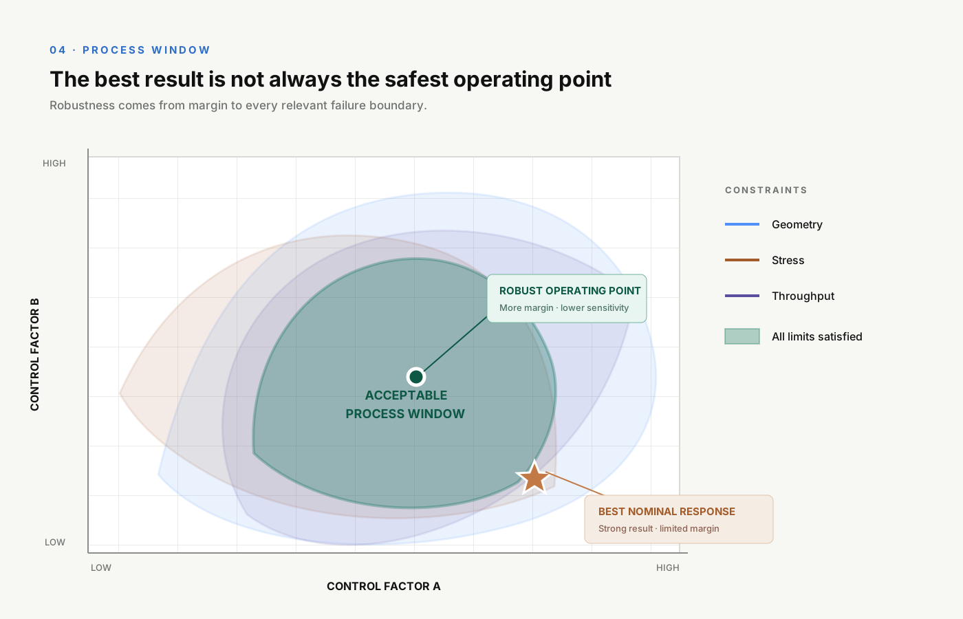
The most impressive result in an experiment is not necessarily the best operating condition.
Suppose a response reaches its ideal value near the edge of the tested region. If a small change in temperature, pressure or material condition moves the output beyond its acceptance limit, the apparent optimum is fragile. A slightly less impressive nominal result located on a flatter part of the response surface may produce higher yield and more predictable device performance.
A process window is the region in which all critical outputs satisfy their requirements. It is created by overlaying constraints, not by optimizing one response in isolation.
For example, the acceptable region may simultaneously require dimensional accuracy, a compatible sidewall profile, stress below a deformation limit, adequate selectivity, practical throughput and no unacceptable damage to materials already on the wafer.
The robust operating point should be selected with expected noise in mind. Depending on the physics, it may be near the geometric center of the acceptable region, on a low-sensitivity plateau, or deliberately offset to protect against a known drift direction.
This is a deeper objective than “finding the optimum.” NIST's discussion of robust experimentation describes searching for regions where the response surface is flatter and therefore less sensitive to difficult-to-control inputs.4
7. Challenge the process with realistic variation
After an operating region has been identified, confirmation at the nominal condition is necessary but insufficient. The process should be challenged with the variation it is expected to encounter.
Relevant sources may include wafer position, different days or batches, material lots, chamber state, pattern density, device geometry, operators and delays between sensitive steps.
The qualification plan should be risk-based. There is no universal number of wafers or batches that proves robustness for every MEMS process. The necessary evidence depends on process maturity, failure severity, cost, expected production volume and how close the operating point lies to its limits.
It is useful to describe evidence in stages:
- Feasibility: an acceptable device can be produced.
- Short-term repeatability: repeated runs under nominal conditions remain acceptable.
- Robustness: expected sources of variation do not push critical outputs beyond their limits.
- Transfer readiness: the process can be executed and interpreted without dependence on undocumented knowledge.
Only a stable process should be evaluated for capability. NIST defines process capability by comparing the natural variability of a stable process with its specification limits.6 This is different from demonstrating that a few measurements fall inside specification.
It is equally important to distinguish specification limits from control limits. Specifications express what the device needs to function; control limits describe the behavior of the process over time. A process can be statistically consistent and still produce an unacceptable device, or meet specification temporarily while showing evidence of a shift.7

8. Standardize the process and monitor what matters
Once the process is accepted, its knowledge must be made durable.
A recipe records equipment instructions. A process specification adds input requirements, critical outputs, operating ranges and acceptance limits. A work instruction captures execution details. An inspection plan defines what is measured, where and how often. A reaction plan states what happens when a control or specification limit is exceeded. Change control protects the established evidence when materials, equipment, geometry or sequence are modified.
The aim is not to document every action with equal intensity. Monitoring should focus on the inputs and outputs that are physically linked to device risk. A parameter that is easy to record but weakly connected to performance should not displace a difficult but critical measurement.
Process history is particularly valuable when low volumes make gradual drift difficult to recognize. Trends across days, wafers and maintenance events may reveal behavior invisible within one run. When a material, tool or design changes, the dependency map identifies which parts require renewed qualification.
Engineering principle
A process is not fully transferred when another person receives the recipe. It is transferred when they also receive the acceptance logic, measurement method, known sensitivities and reaction plan.
Before calling a MEMS process optimized
Use the following questions as a final review:
- Is success defined at the device level?
- Are the critical process outputs measurable?
- Is the measurement uncertainty small enough for the intended decision?
- Are upstream and downstream dependencies documented?
- Is the baseline reproducible?
- Have the most influential control and noise factors been identified?
- Was the experimental design appropriate for the expected interactions?
- Does an acceptable multi-response process window exist?
- Has the selected condition been challenged across realistic variation?
- Are specifications, monitoring and reaction rules documented?
If several answers remain uncertain, the process may still be promising. It should simply be described accurately: as a feasibility result, a provisional recipe or a process still under development.
Stability is engineered
Robust MEMS processing is not created by repeatedly adjusting parameters until a good device appears. It is created by connecting device requirements to measurable outputs, understanding how fabrication steps interact, designing experiments that resolve the important uncertainties and selecting an operating region that tolerates expected variation.
The change in mindset is simple but consequential: the goal is not a recipe that works under ideal conditions. The goal is a process whose behavior is understood well enough to remain acceptable when conditions are no longer ideal.
That is the difference between producing a successful prototype and developing a process that can support reliable engineering.
References
- 1. M. F. Niekiel et al., “What MEMS Research and Development Can Learn from a Production Environment,” Sensors, 23(12), 5549, 2023. https://doi.org/10.3390/s23125549
- 2. NIST/SEMATECH, “Measurement Process Characterization: Approach to Uncertainty,” e-Handbook of Statistical Methods.
- 3. NIST/SEMATECH, “What Is Experimental Design?,” e-Handbook of Statistical Methods.
- 4. NIST/SEMATECH, “What Are the Uses of DOE?,” e-Handbook of Statistical Methods.
- 5. NIST/SEMATECH, “Response Surface Model Example: CVD Uniformity and Stress,” e-Handbook of Statistical Methods.
- 6. NIST/SEMATECH, “What Is Process Capability?,” e-Handbook of Statistical Methods.
- 7. NIST/SEMATECH, “What Are Variables Control Charts?,” e-Handbook of Statistical Methods.
Related engineering work
Integrated Colloidal Scanning Probe Platform
Process integration, fabrication evidence and device-level validation.
Engineering conversation
Working on a MEMS process-development challenge?
ali.hp.shafaghi@gmail.com