Featured Project 02
PhD Research · MEMS Design & Characterization
Low-Power SU-8 Thermal Actuator
Designed, fabricated, and experimentally validated a low-power SU-8/Cu bimorph actuator achieving 63 µm out-of-plane displacement at 36 mW. Characterized in air, it was developed for potential use in fluidic and underwater environments.
63 µm
Maximum measured displacement
36 mW
Input power
≈200 ms
Simulated response
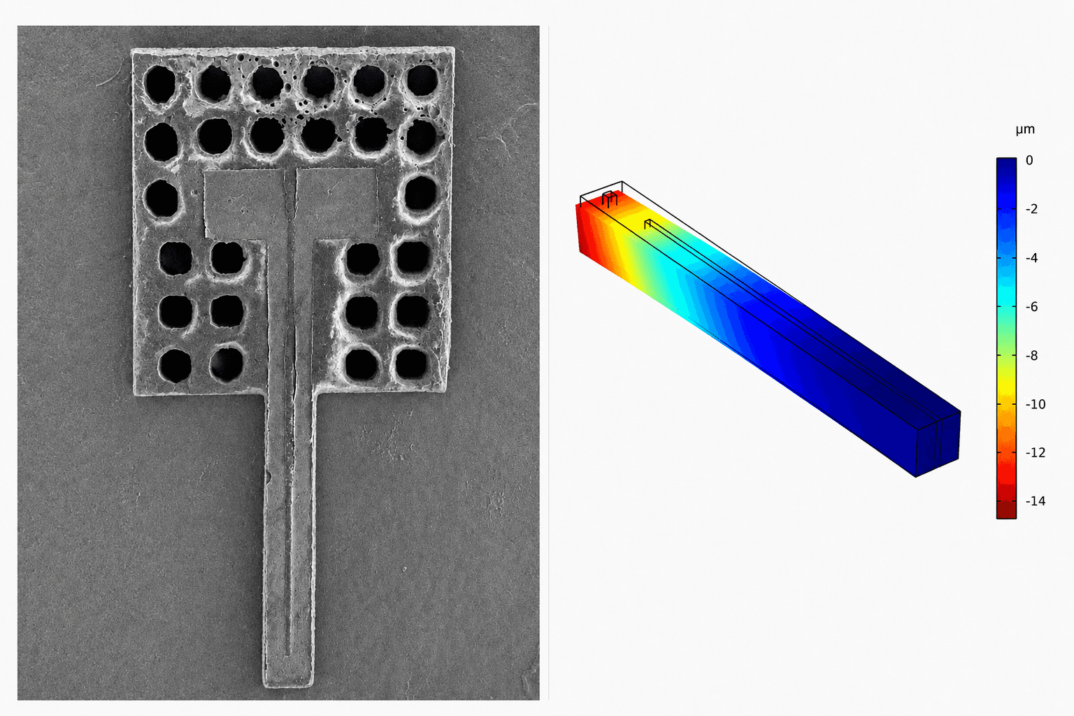
Fabricated SU-8 thermal actuator and simulated displacement profile
I led the multiphysics modeling, mask design, microfabrication, and experimental characterization of the actuator.
01 — The Engineering Challenge
Large motion. Minimal power.
Thermal microactuators can generate useful force, but power consumption and heat accumulation often constrain compact systems. The goal was to translate controlled Joule heating into substantial out-of-plane motion using an SU-8/Cu bimorph.
01
Power efficiency
Generate useful displacement at milliwatt-level input power.
02
Out-of-plane motion
Convert in-plane Joule heating into predictable vertical bending.
03
Thermal operating window
Maximize travel without crossing the device's damage boundary.
Experimental Scope
Characterized in air. Fluidic and underwater operation remained a proposed future application.
02 — Coupled Multiphysics Model
Three physics. One predictive model.
A coupled COMSOL model linked electrical current, Joule heating, heat transfer, and structural deformation—allowing displacement to be predicted before fabrication.
01
Electrical
Current density · Electric field · Potential
02

Thermal
Joule heating · Conduction · Convection
03
Structural
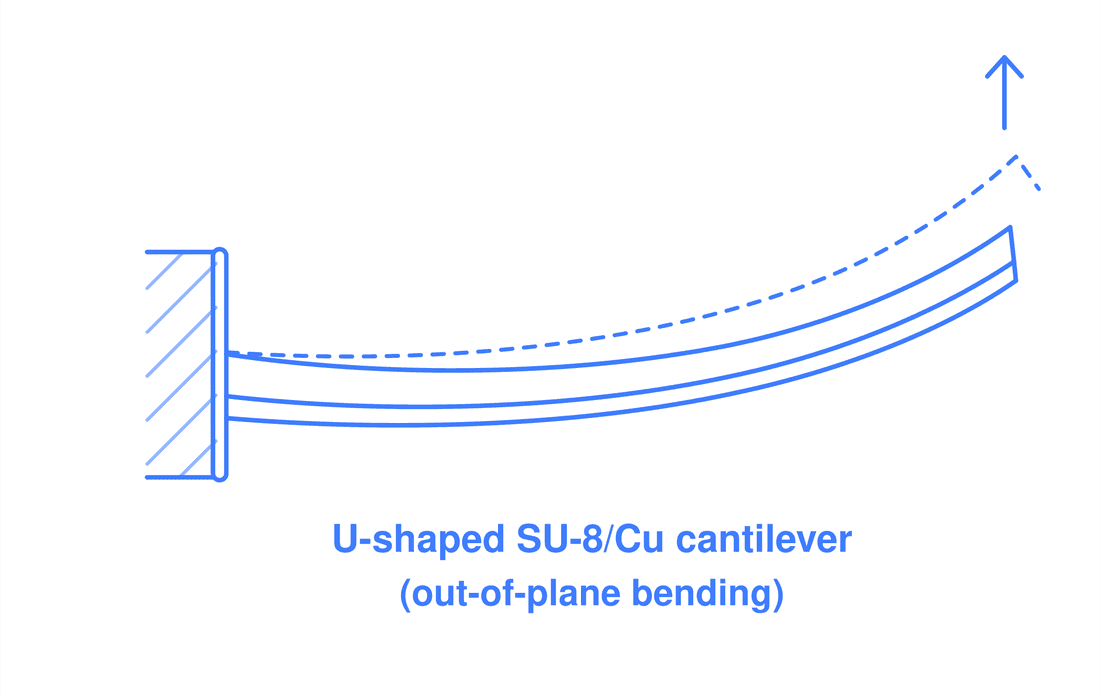
Thermal expansion · Out-of-plane displacement
Boundary Conditions
Terminal and ground · Heat transfer to ambient air · Fixed anchor
Model Confidence
Mesh-independence analysis verified solution stability before parameter sweeps.
03 — Geometry & Performance Optimization
Pattern the structure. Shape the motion.
Alternative geometries were evaluated in COMSOL to understand how patterning changes stiffness, thermal–stress distribution, and directional deflection.
Simulation Design Space
Type 0
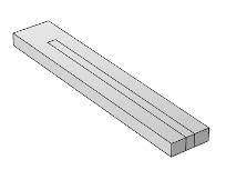
Type 1
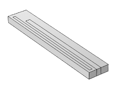
Type 2
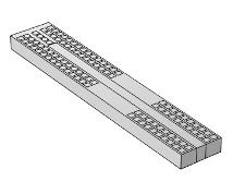
Type 3
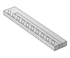
Simulated Tip Response
Simulation Study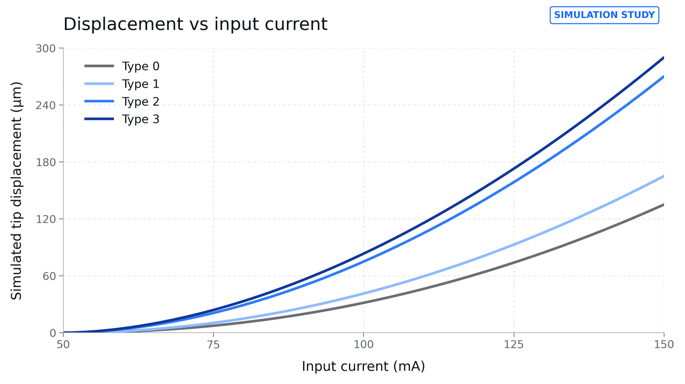
Patterning increased bending potential—but also changed lateral motion and stress localization.
Stiffness
Slots and openings redistributed structural compliance.
Directional Control
Geometry altered x-, y-, and z-direction response.
Design Decision
The standard U-shaped configuration was carried into experimental validation.
04 — From Mask Design to Fabricated Device
Two masks. One released bimorph.
An aligned metal-and-polymer process translated the simulated geometry into a suspended SU-8/Cu actuator.
Fabrication Sequence
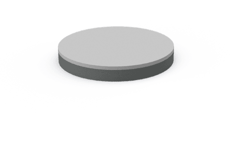
01
Sacrificial Layer
PECVD SiO₂ on Si
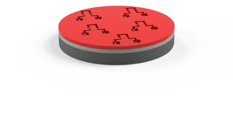
02
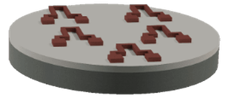
Heater Lithography
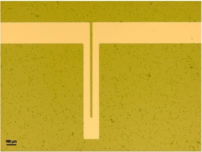
Pattern the U-shaped active layer
03
Cr/Cu Deposition
Thermal evaporation
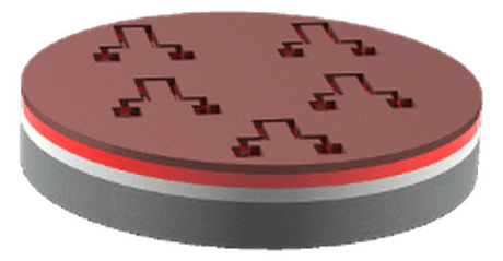
04
Lift-off
Retain heater and contact pads
05
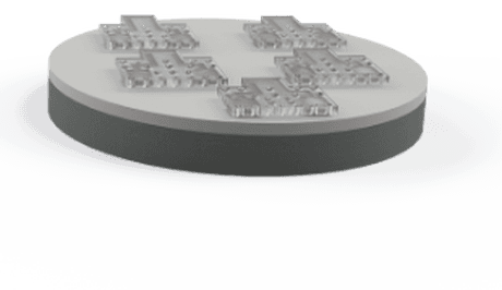
SU-8 Patterning
Form the passive cantilever and release holes
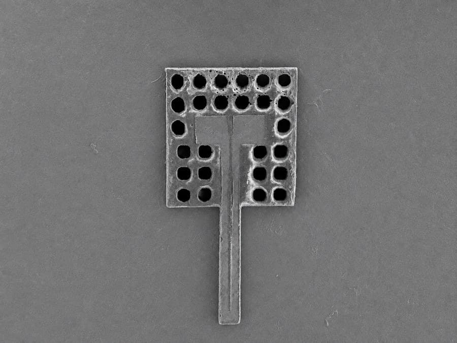
Fabrication Evidence
Active Layer
Passive Layer
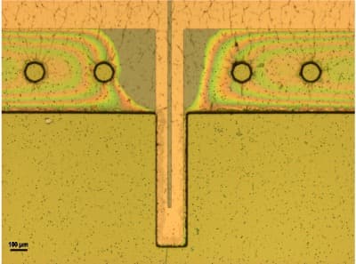
Released Device
05 — Experimental Characterization
Measuring out-of-plane motion.
The fabricated actuator was contacted on a probe station and driven through a controlled DC power sweep. Tip displacement was tracked optically while the device was characterized in air.
DC Input
Probe-Station Contact
Optical Readout
Input Control
Current and electrical power sweep
Measured Output
Out-of-plane tip displacement
Test Environment
Characterized experimentally in air
Underwater operation was proposed as a future application and was not experimentally demonstrated.
06 — Model-to-Hardware Validation
The model predicted the hardware.
Steady-state measurements followed the simulated trend across the tested power range, providing experimental confidence in the coupled multiphysics model.
Tip displacement vs. input power
Simulation–experiment comparison
63 µm
Maximum measured displacement
at 36 mW input power
Measured steady-state points
Strong agreement between simulation and experiment validated the design approach; remaining differences were attributed to environmental and measurement effects.
07 — Operating Boundary & Engineering Lessons
Performance has a thermal ceiling.
High-power testing exposed a geometry-dependent boundary between useful deflection and irreversible damage.
Device-specific operating boundary
Long Actuator
63 µm measured at 36 mW
Short Actuator
Burning observed above 30 mW
Presentation evidence also documents a damaged-device example around 40 mW.
Observed Failure Evidence
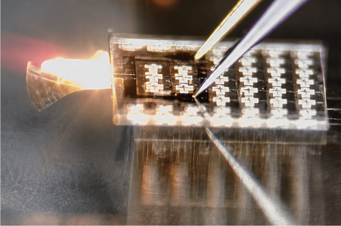
High-power damage observation · experimental evidence
Irreversible DamageGeometry Matters
Longer actuators produced greater displacement.
Power Limits Are Device-Specific
The safe operating margin changes with actuator length.
Next Iteration
Pattern the active layer and apply geometry-specific current limiting.
These observations define an engineering boundary—not a universal rated limit.