Featured Project 03
Silicon Microfluidics
Cavitation-on-Chip Microfluidic Reactor
An eight-orifice silicon–glass reactor engineered to trigger cavitation at reduced inlet pressure and produce several distinct two-phase flow regimes on a single chip.
My Role
Device co-development · Experimental testing · High-speed imaging · Flow analysis
First author · Physics of Fluids · 2021
I co-developed the eight-orifice device and led the experimental testing, high-speed flow imaging, and flow-regime analysis presented in this work.
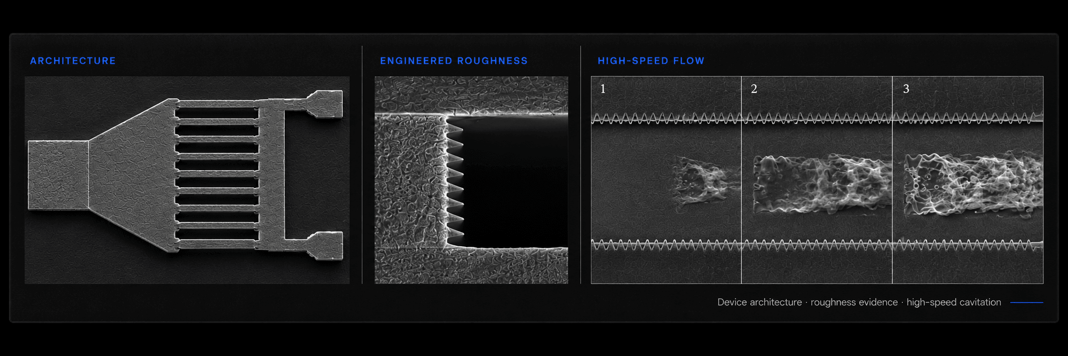
Scanning-electron micrographs of the eight-orifice device, the engineered orifice roughness, and high-speed imaging of the resulting cavitating jets.
8
Parallel micro-orifices
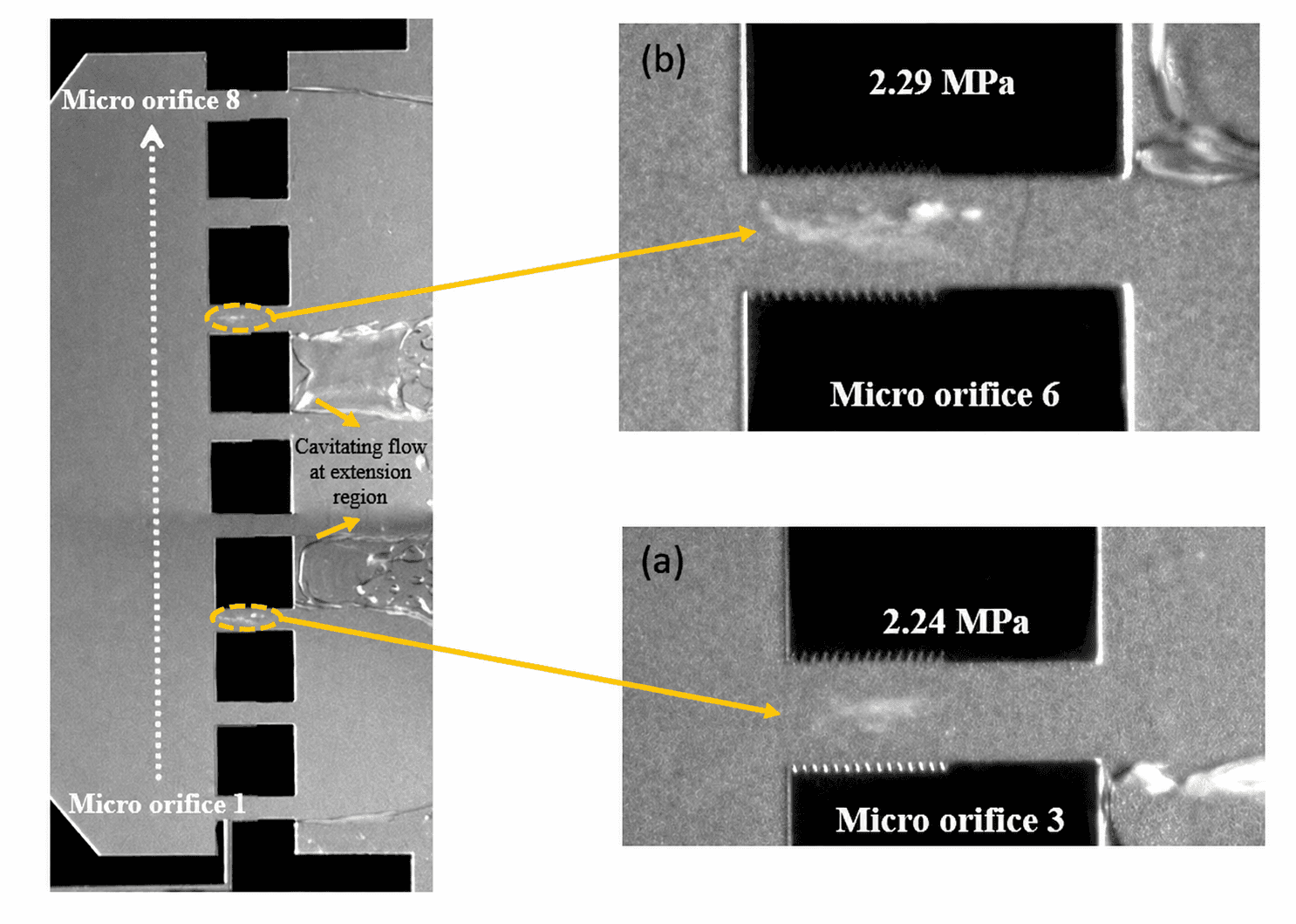
2.24 MPa
Cavitation inception pressure
≈46%
Reduction vs. reference geometry
7,000 fps
High-speed imaging frame rate
01 — The Engineering Challenge
Trigger cavitation sooner. Unlock more flow regimes.
The objective was to initiate hydrodynamic cavitation at a lower upstream pressure than a conventional single-orifice geometry, while giving a single chip access to several distinct two-phase flow patterns.
01 · Lower the threshold
Reduce the pressure needed to initiate cavitation.
A single-orifice reference geometry required 4.13 MPa of upstream pressure before cavitation would begin.
Desired inception window
4.13 MPa
Single-orifice reference
02 · Expand flow diversity
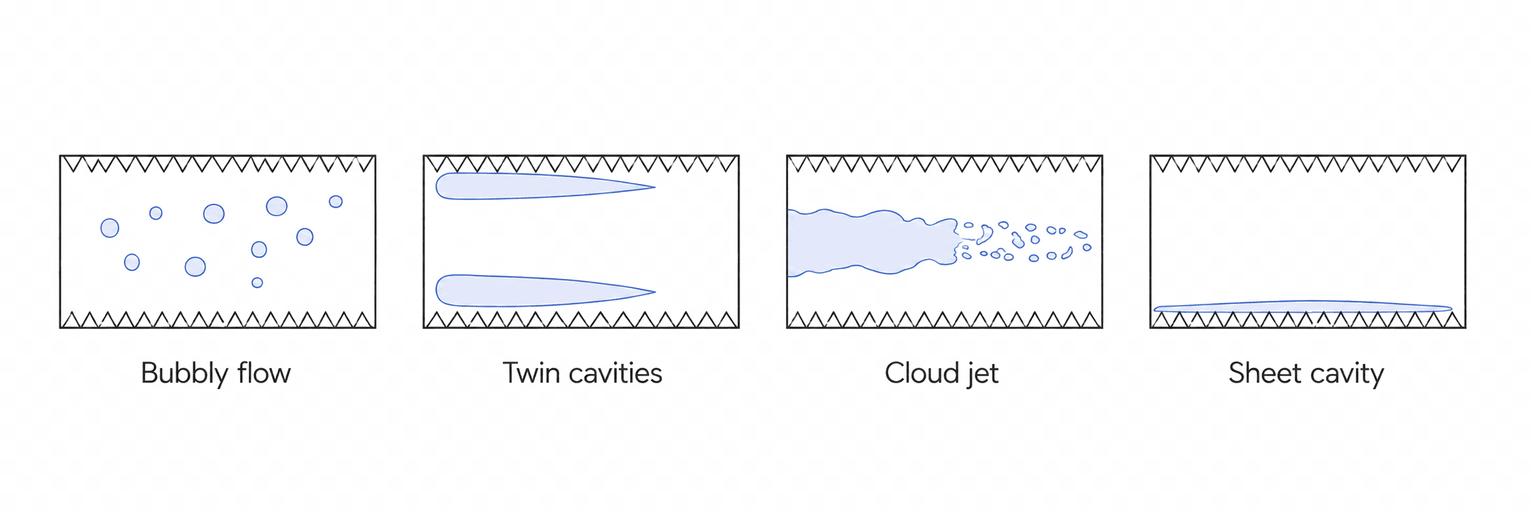
Produce multiple distinct flow regimes from a single chip.
Flow morphology needed to change without adjusting the external operating conditions.
The Target
Initiate cavitation at a lower pressure while producing several useful flow regimes on one chip.
02 — Eight-Orifice Reactor Architecture
One inlet, split eight ways.
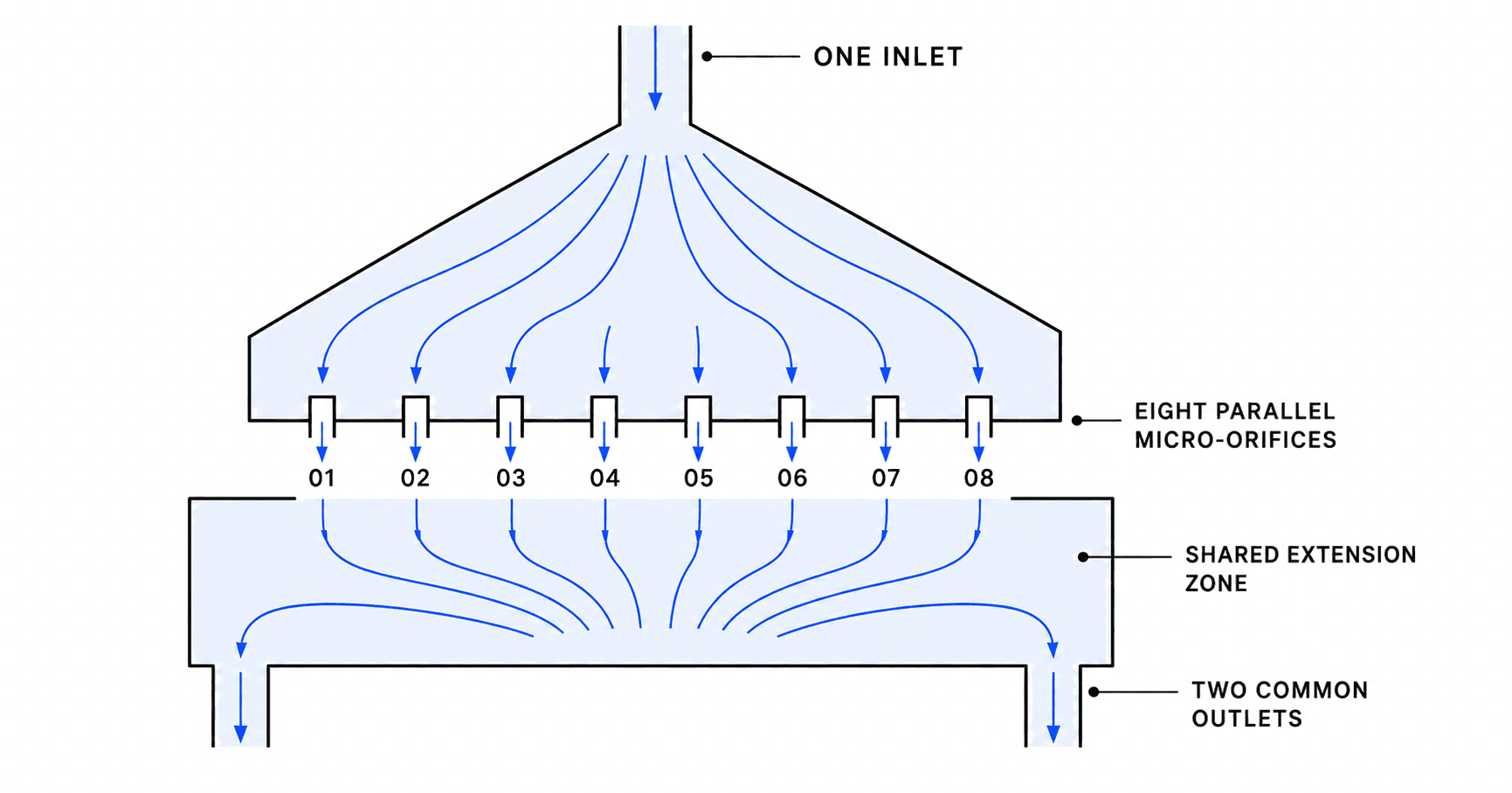
Flow entered through a single expanding chamber that divided into eight parallel micro-orifices before recombining in a shared extension zone. The inlet geometry set the velocity distribution across the array, while engineered sidewall roughness gave each channel a repeatable nucleation site.
01 Parallelization
Eight parallel branches multiply the number of active cavitation sites within a single compact reactor.
02 Functional sidewalls
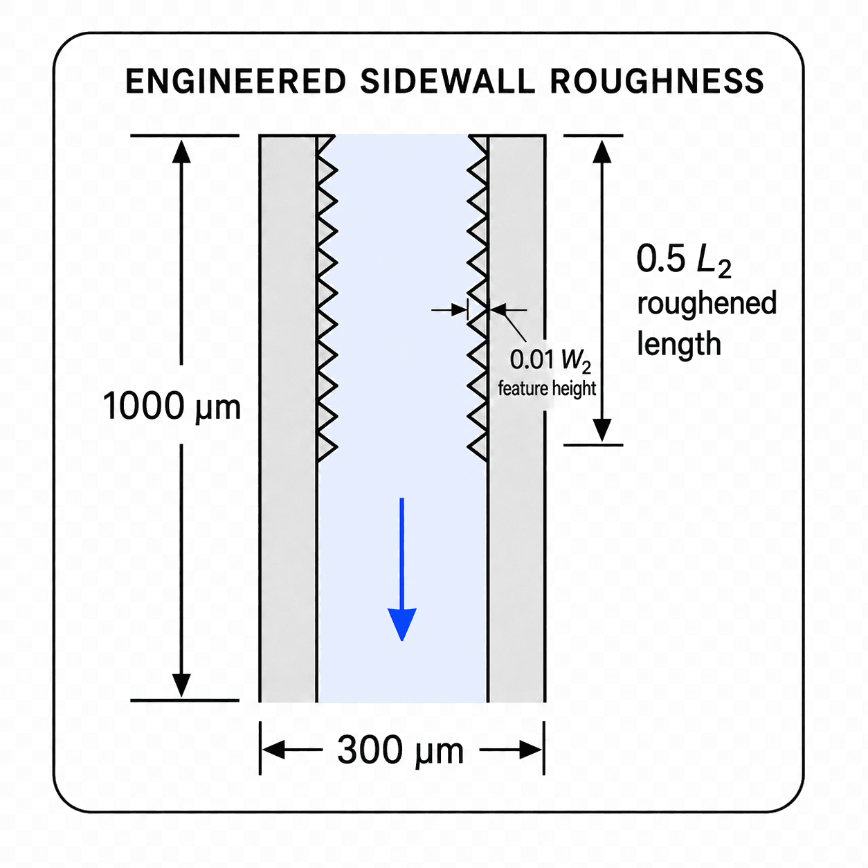
Triangular sidewall features, evenly spaced along each channel, promote heterogeneous nucleation at the walls.
03 Geometry-shaped distribution
The expanding entrance geometry produces channel-to-channel velocity variation even under a single inlet pressure.
8
Parallel orifices
300 µm
Orifice width
1000 µm
Orifice length
50 µm
Channel depth
03 — From Geometry to a Silicon–Glass Device
Silicon etched. Stress managed. Chip sealed.
The eight-orifice layout became a closed microreactor through oxide masking, deep silicon etching, and backside stress control, sealed by anodic bonding to glass and integrated into a five-port fluidic package.
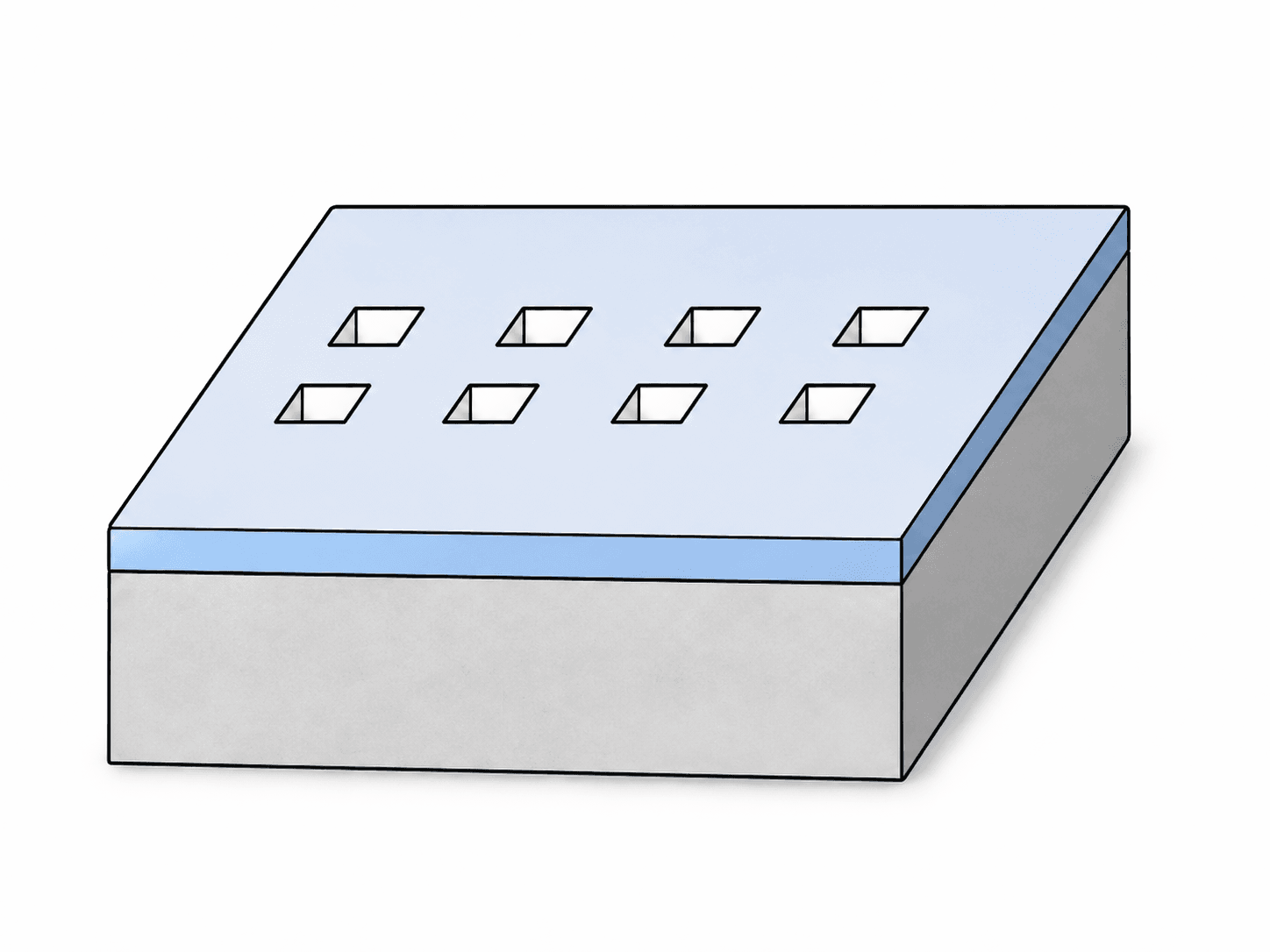
Oxide Hard Mask
250 µm Si · 500 nm SiO₂
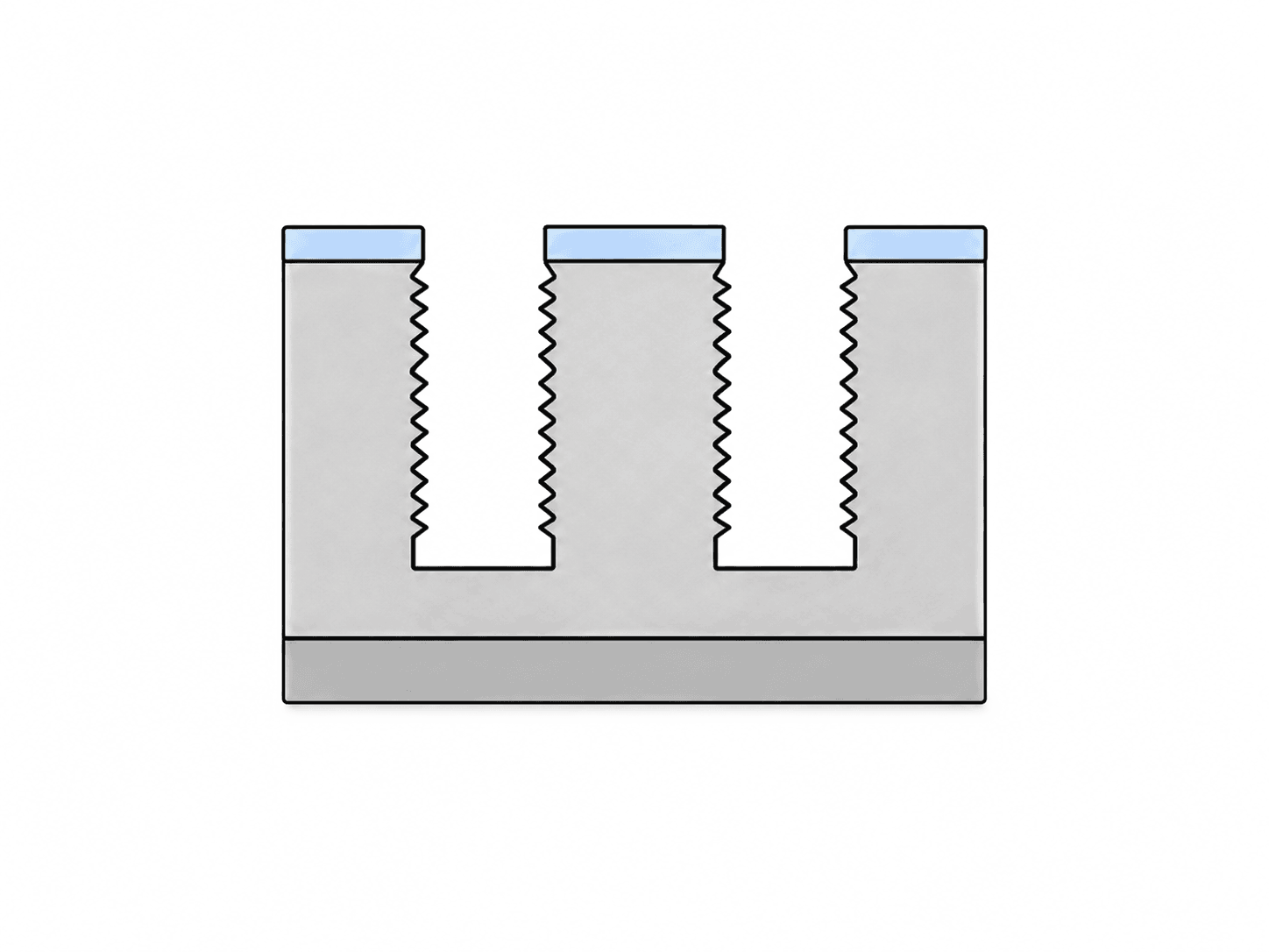
Deep Silicon Etch
Deep reactive-ion etching transferred the channel geometry and engineered sidewalls into the silicon.
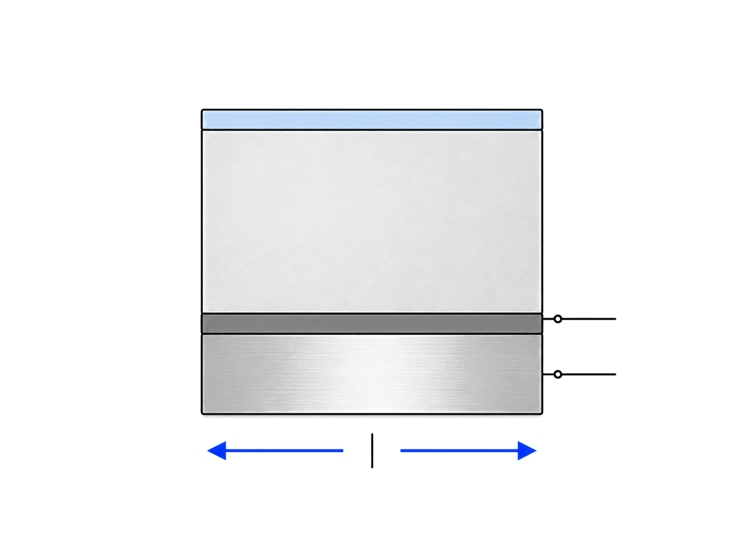
Stress Management
A 10 nm Ti + 2 µm Al backside coating reduced fracture risk during processing.
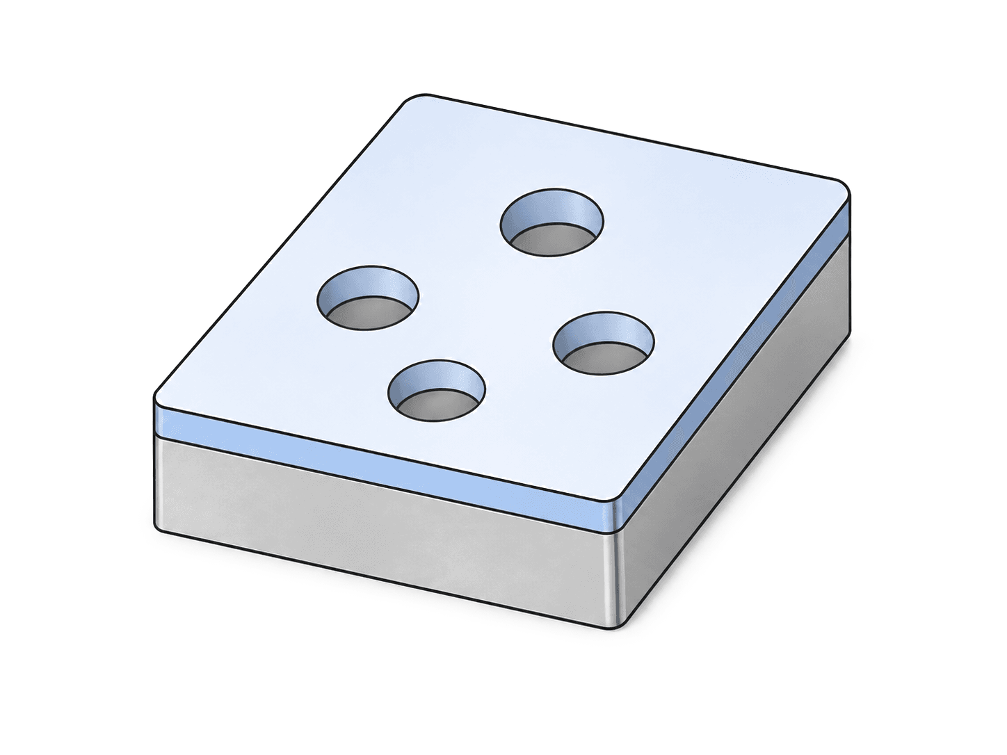
Port Opening + Clean
Inlet, outlet, and pressure ports were opened, and temporary protective films were stripped.
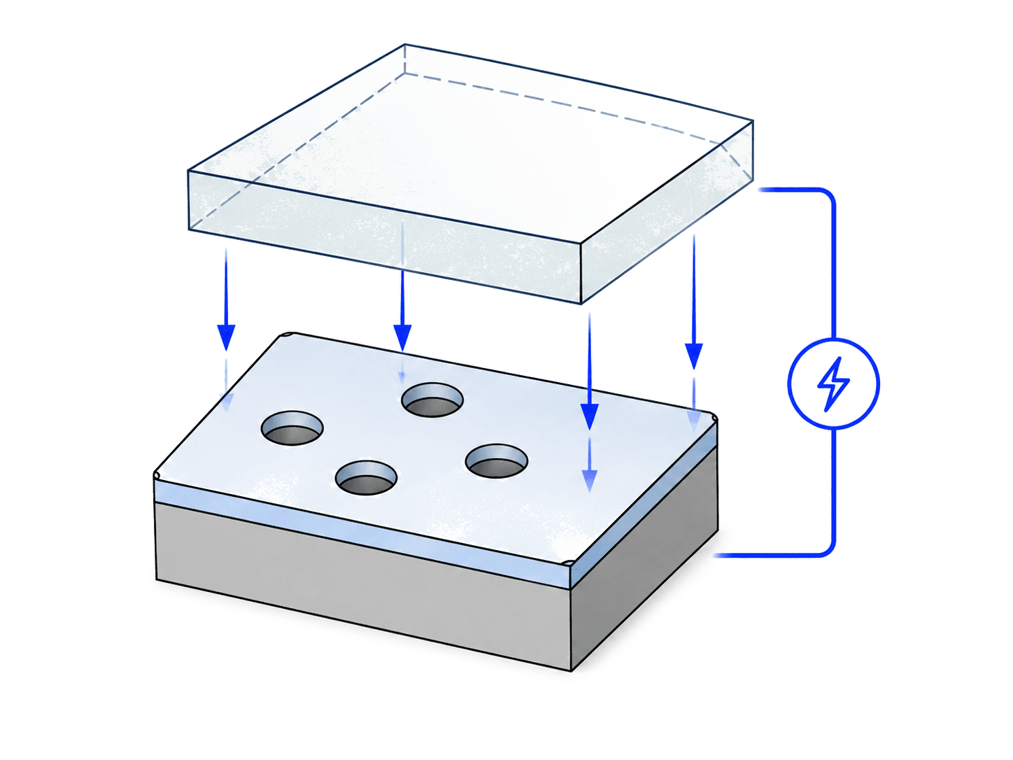
Anodic Bonding
A Borofloat-33 glass lid was anodically bonded to seal the silicon channels.
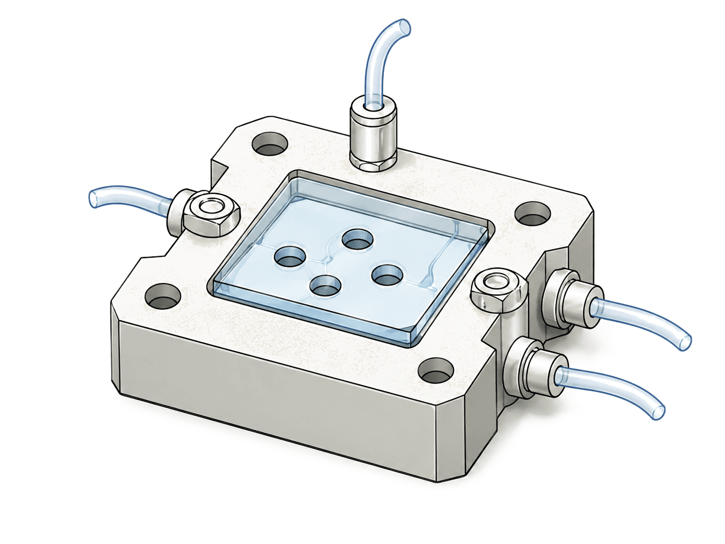
Fluidic Packaging
A five-port holder provided external flow connections and in-line pressure measurement.
Collaborative Fabrication
The silicon micromachining, anodic bonding, and fluidic packaging shown here were executed by the broader project team.
I collaborated on the device geometry and then led the experimental program that followed.
04 — Experimental Characterization
Imaging cavitation at 7,000 frames per second.
A pressure-driven test rig paired controlled flow, the packaged silicon–glass device, back illumination, and high-speed imaging to resolve transient two-phase behavior.
My role — Setup operation · High-speed imaging · Quantitative analysis
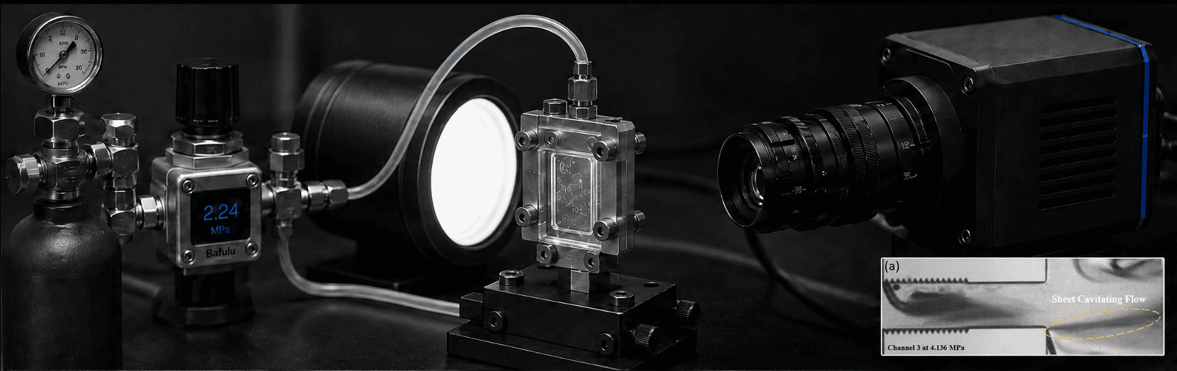
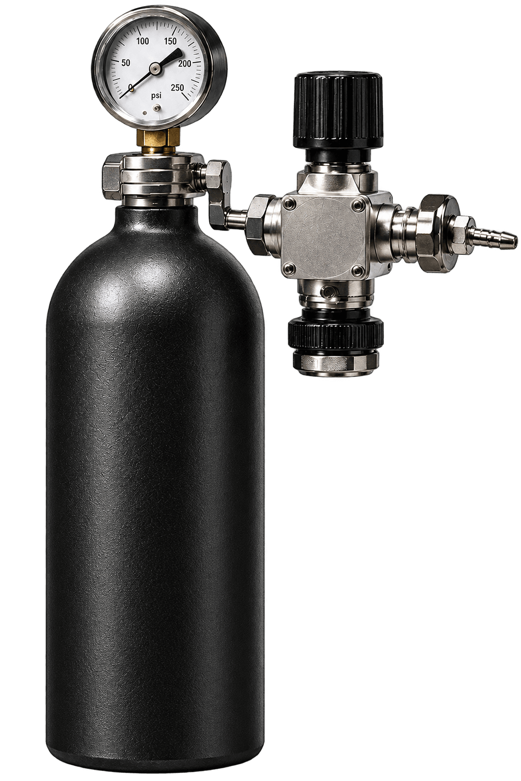
Pressure source
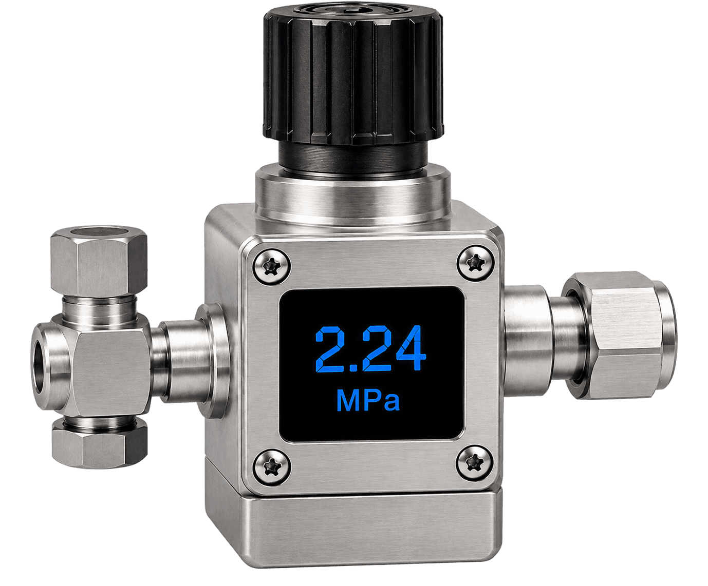
Flow control
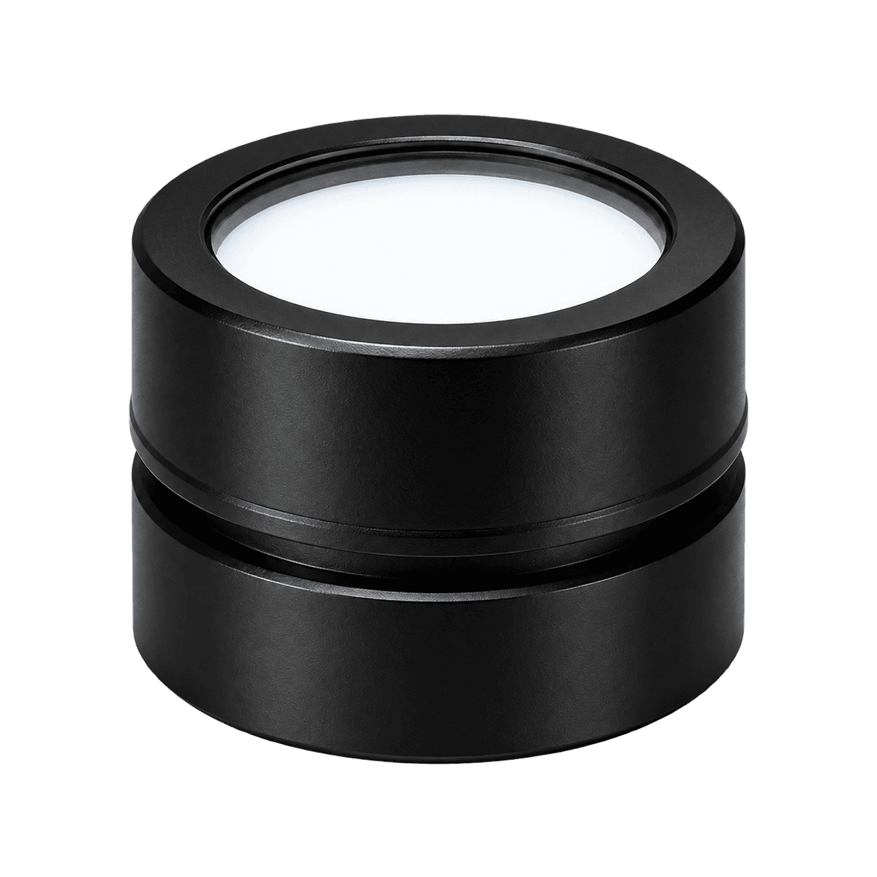
Back illumination
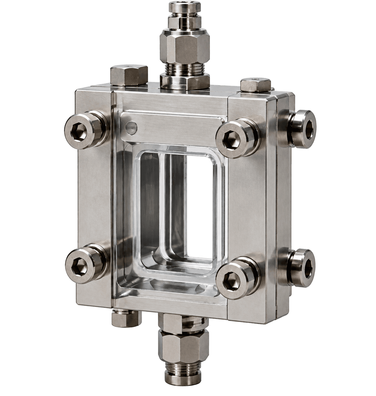
Packaged reactor
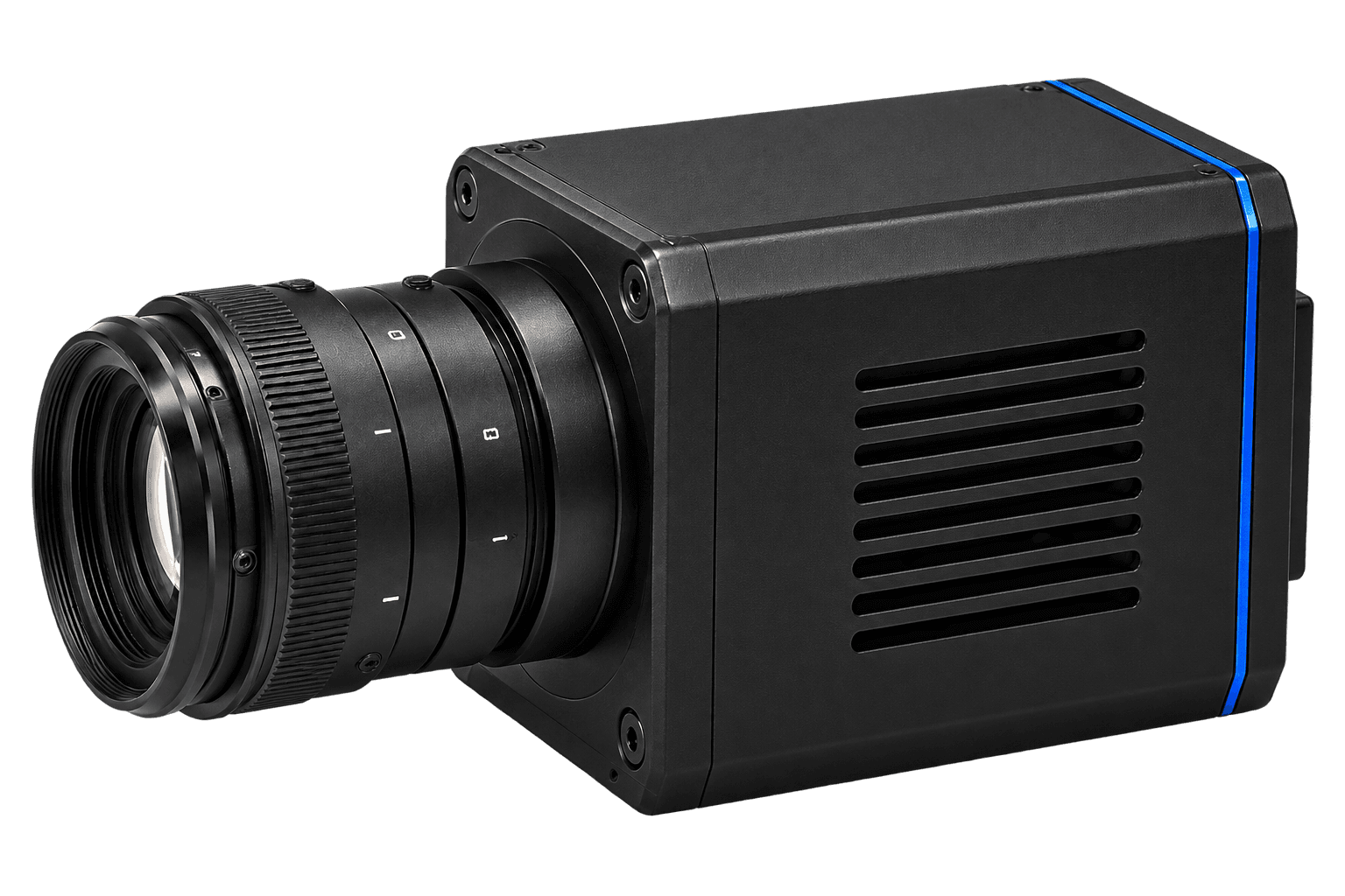
High-speed camera
7,000 fps
Frame rate
1 µs
Exposure time
2.24 MPa
Cavitation inception
05 — Mapping Cavitation Behaviour
From raw frames to a flow-regime map.
My Role
High-speed imaging · Frame analysis · Flow-pattern classification · Quantitative interpretation
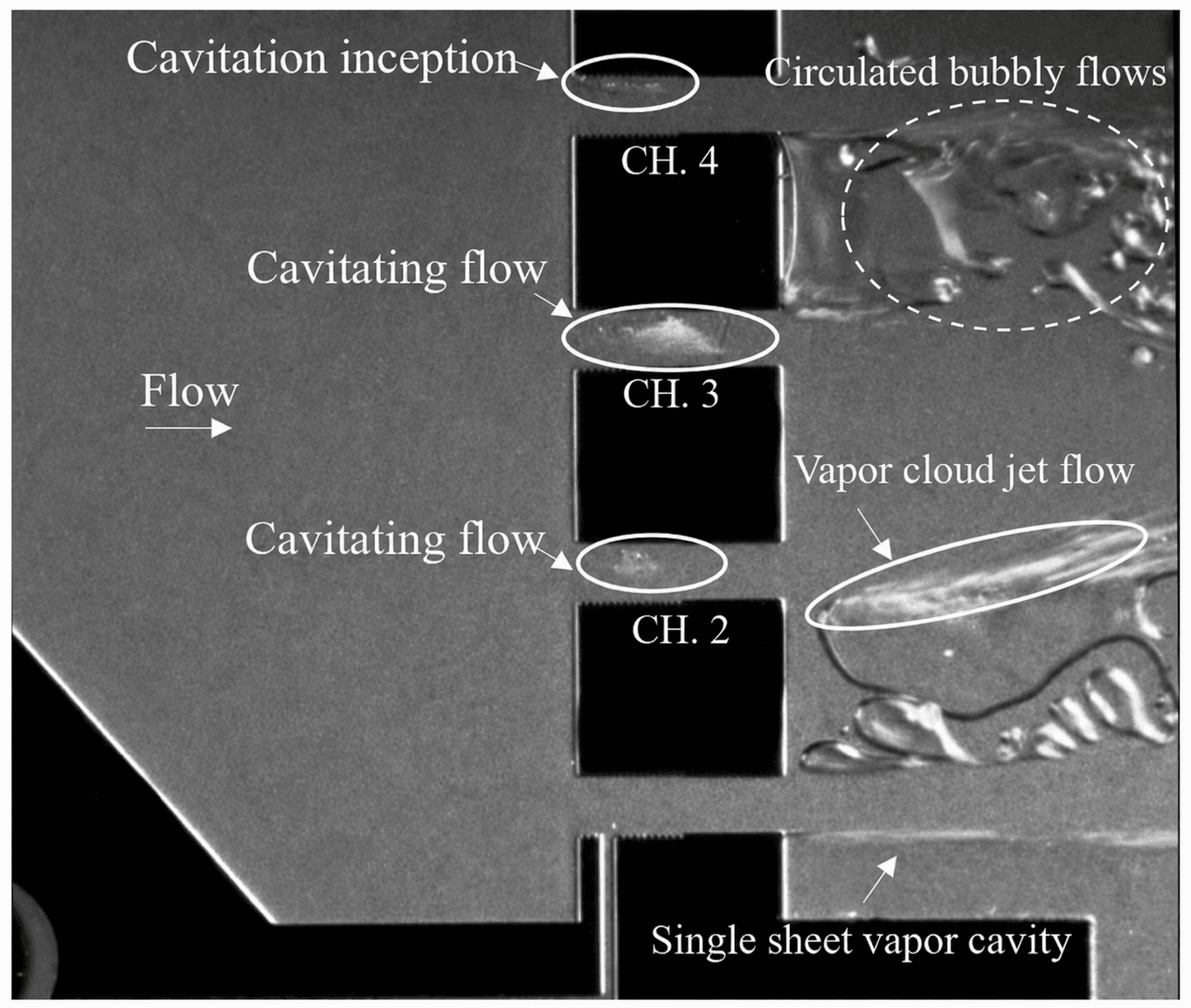
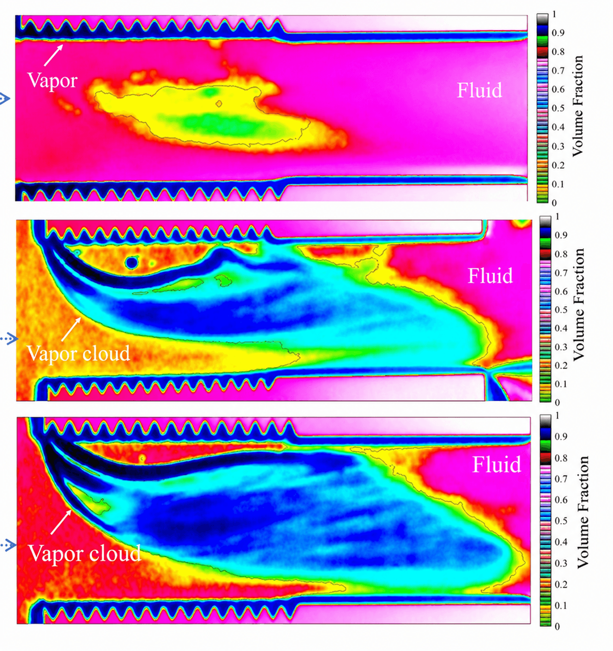
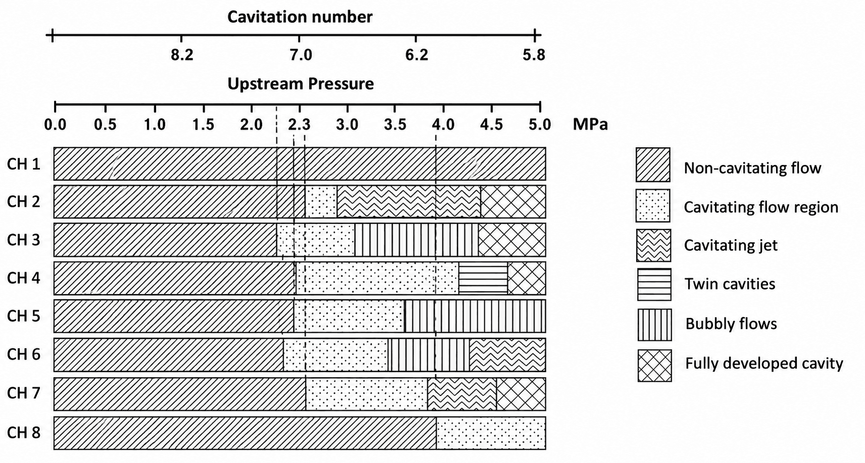
High-speed image sequences were analyzed to detect cavitation inception, classify the evolving flow regime, and quantify vapor development across all eight parallel micro-orifices.
7,000 fps
High-speed capture
8 channels
Parallel comparison
Frame by frame
Void-fraction analysis
06 — Results & Engineering Takeaways
Lower pressure.More useful flow states.
The eight-orifice reactor reached cavitation inception at 2.24 MPa—approximately 46% below the 4.13 MPa single-orifice reference—while supporting several cavitation patterns under the same operating condition.
2.24MPa
Cavitation inception
4.13 MPa
Referenced single-orifice design
2.24 MPa
Eight-orifice reactor
≈46%
Lower
Published pressure response
Source: Published high-speed study of cavitation inception in micro-orifices (data reproduced).
From sheet cavity to fully developed flow
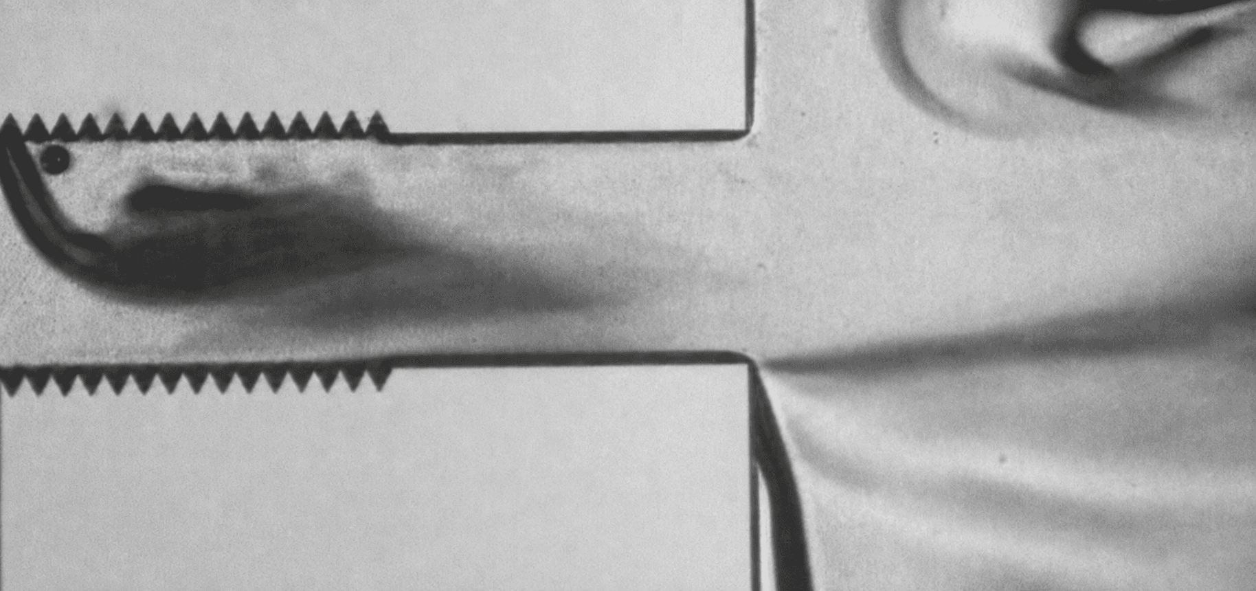
Sheet cavity
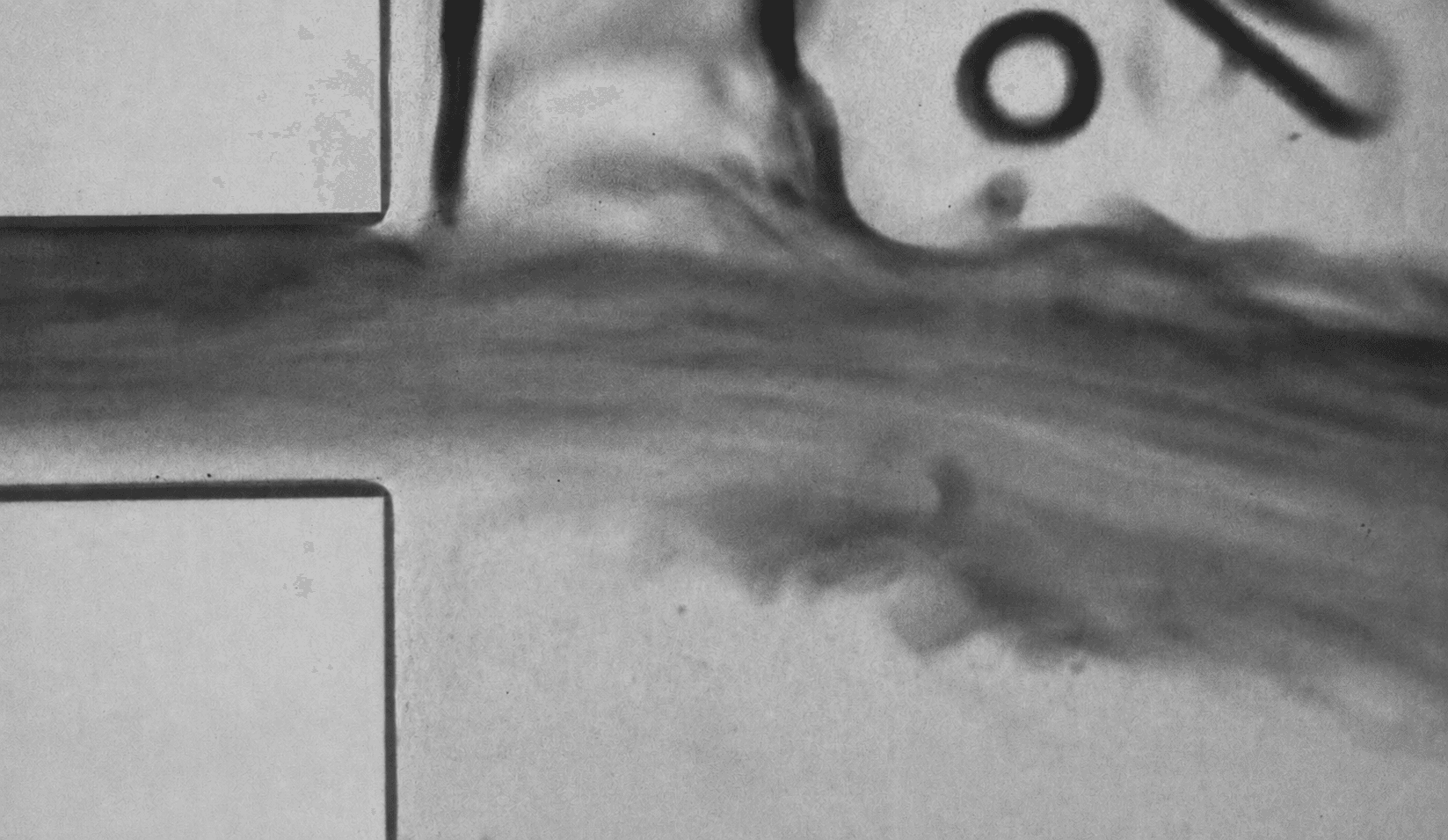
Fully developed oscillating flow
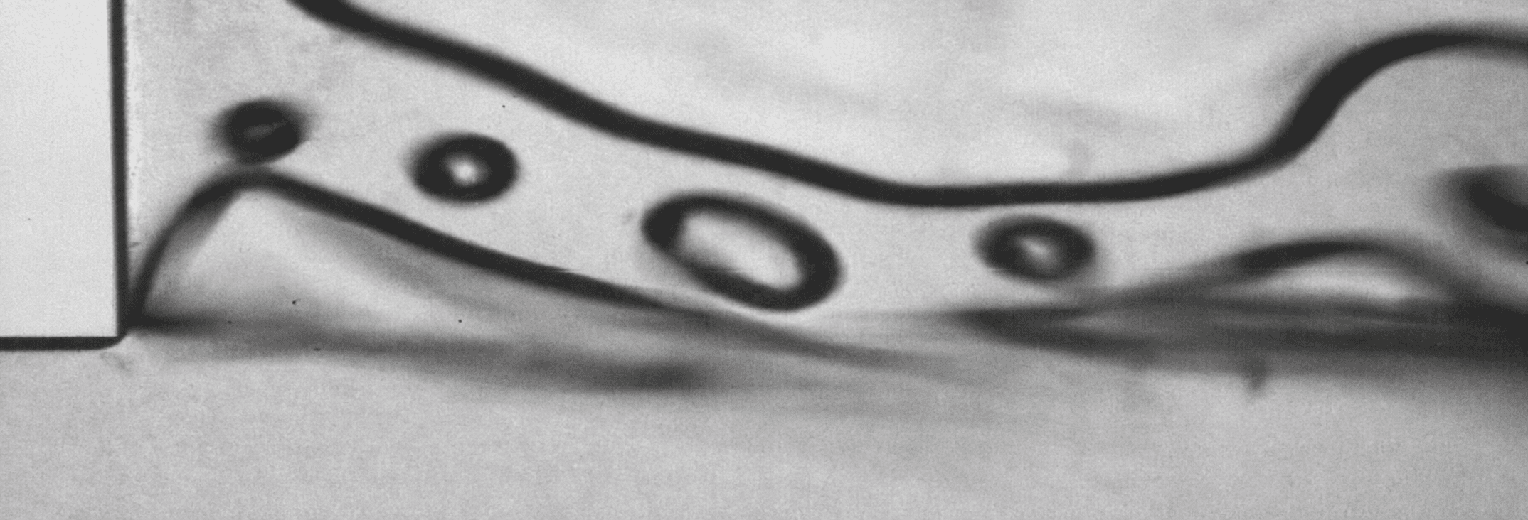
Downstream bubble morphology
Earlier nucleation
Engineered sidewall roughness promoted cavitation at a lower upstream pressure.
Parallel functionality
Eight micro-orifices supported distinct cavitation behaviours within one device.
Evidence-led design
High-speed imaging connected pressure conditions to evolving vapor structures.
My Contribution — Co-developed the concept and geometry · Led experimental characterization · Analyzed the flow behaviour · Led interpretation and writing